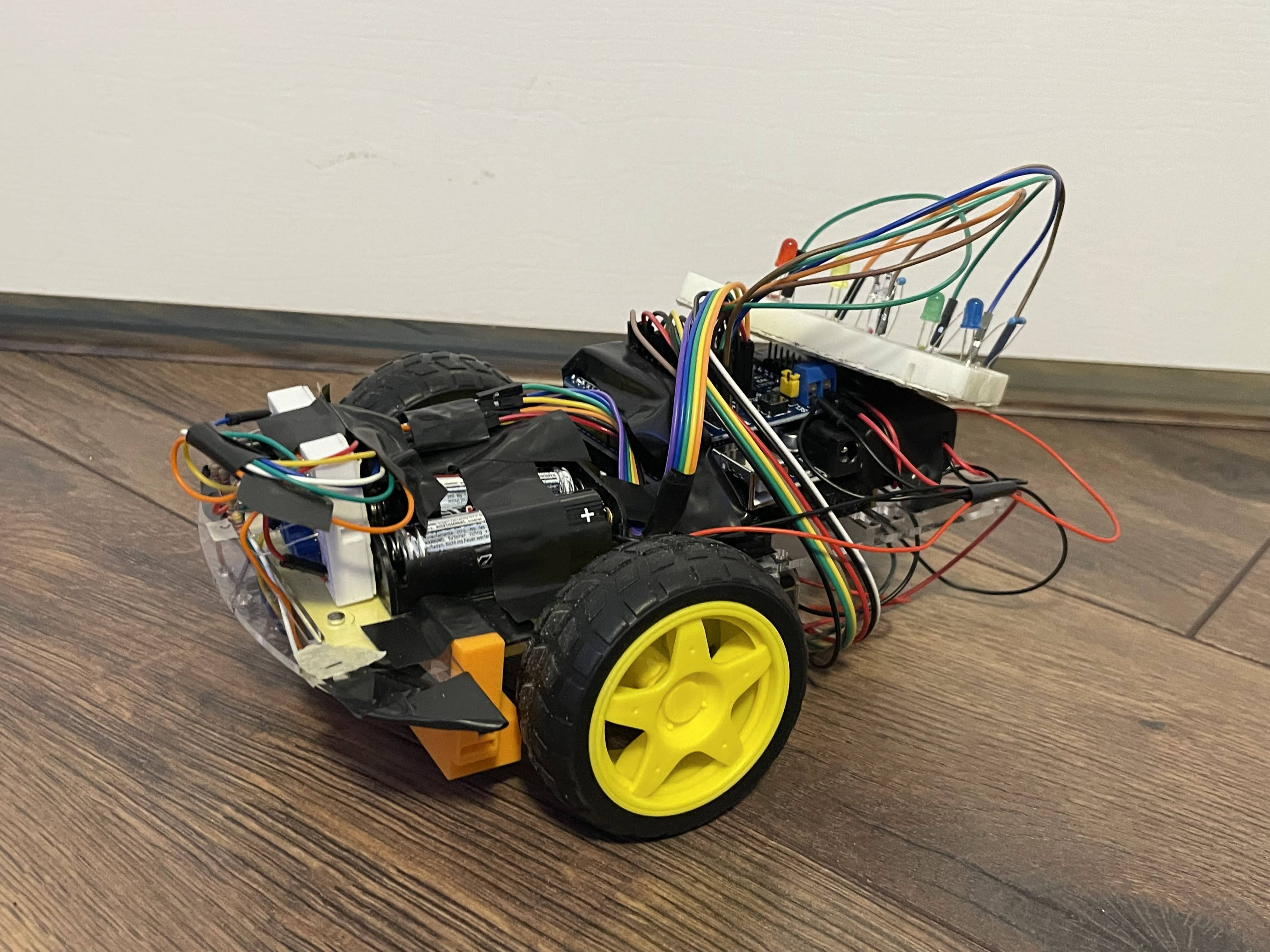
September 2022 - November 2022
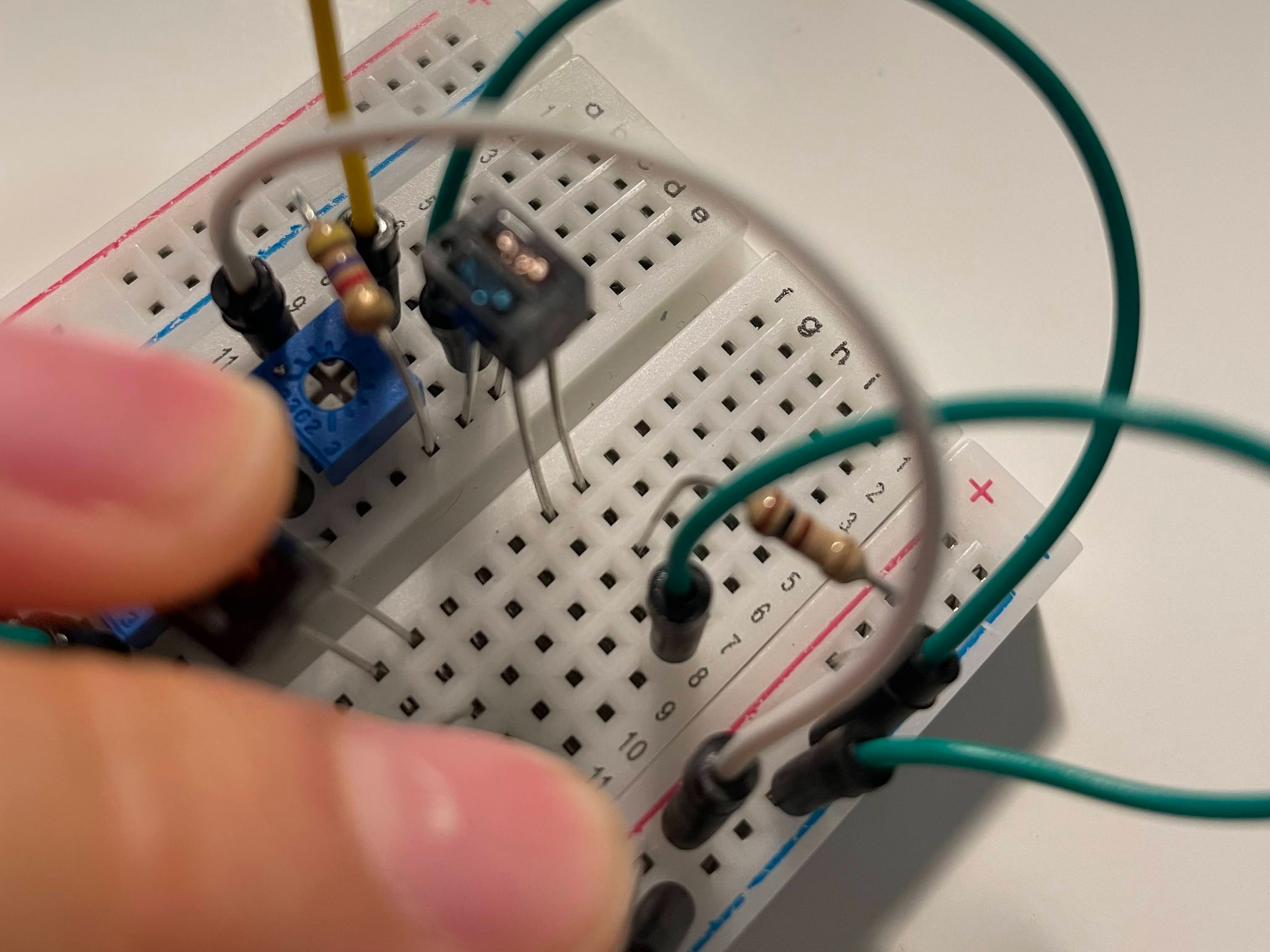
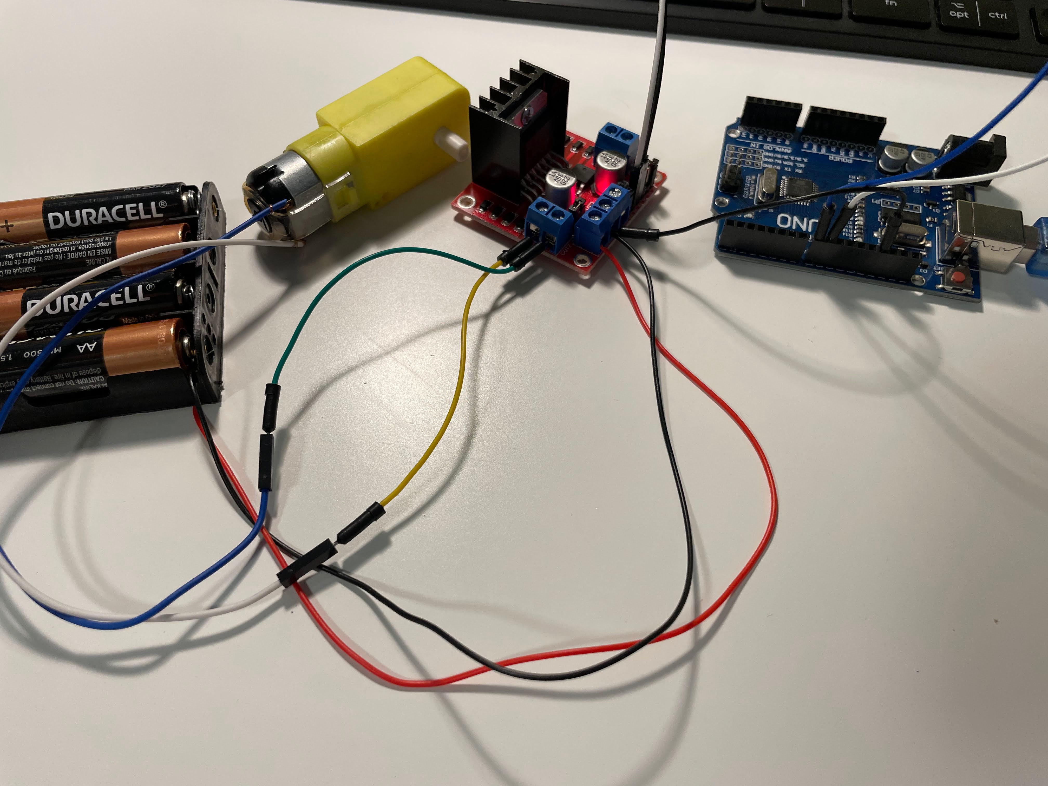
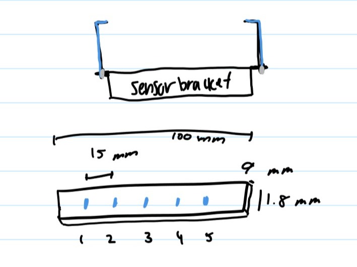
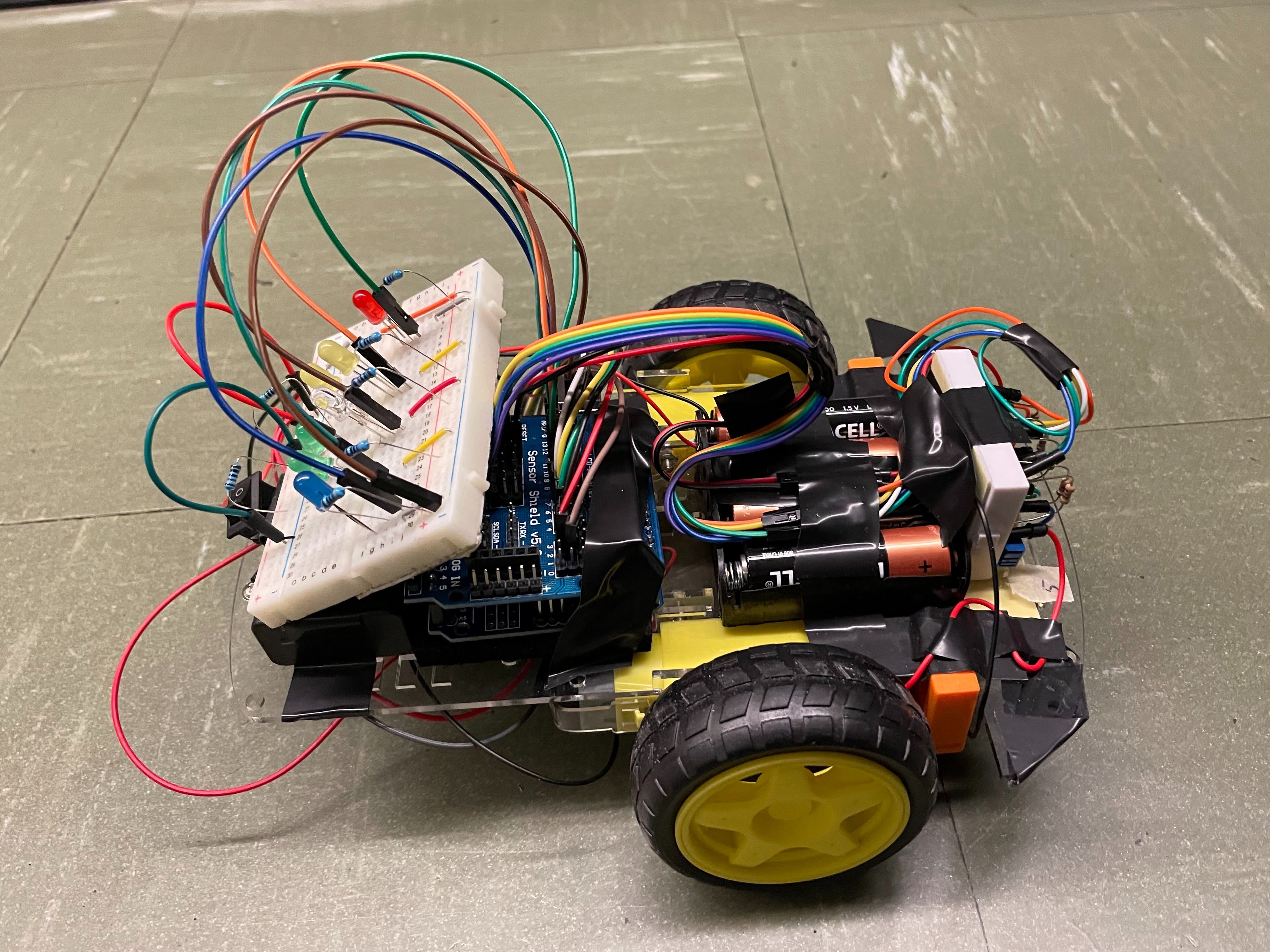
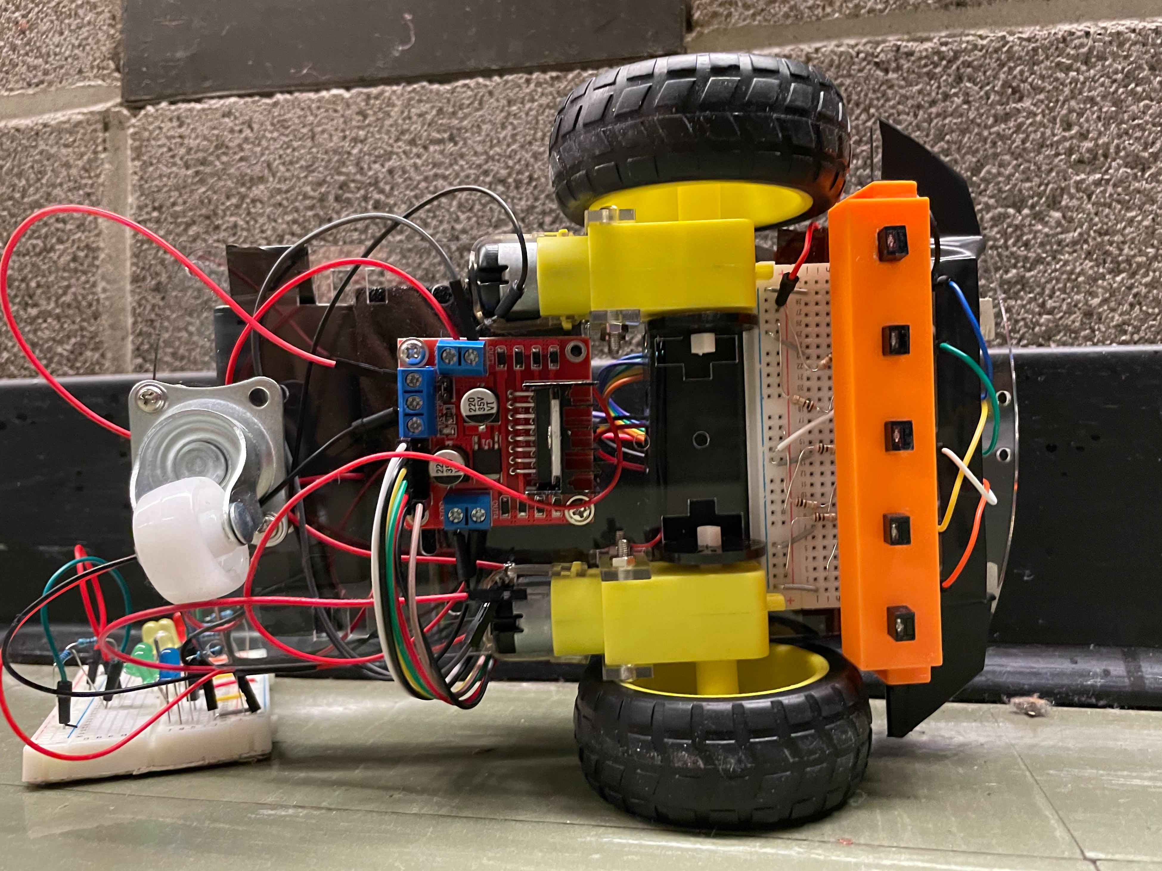
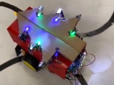
This robot was created for my IGEN 230 course at UBC. It consisted of chassis parts, phototransistors, an Arduino Uno, and other relevant parts.
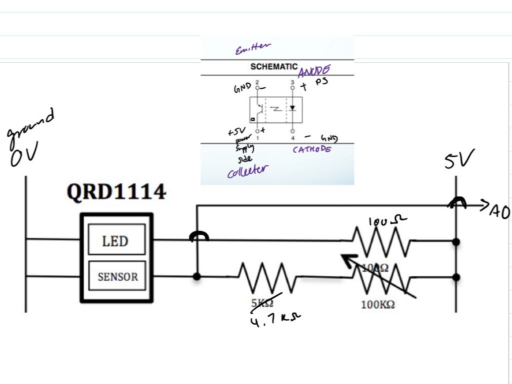
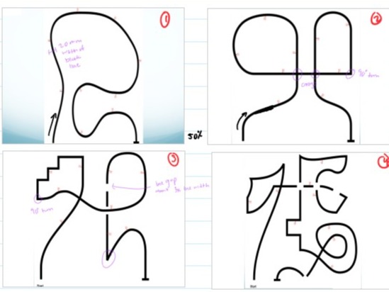
The use of infrared reflective sensors (phototransistors) allowed for the robot to detect the presence of dark lines. An Arduino Uno powered the robot running on a code that I wrote, based off the example our professor provided us.
Design Tests
Prior to connecting any of the components together, the first step was to test each component individually. I began testing the phototransistor (Figure 2) with white and black paper; this allowed me to read the distinctive voltages on the Arduino serial monitor. Then I connected a motor to the h-bridge (Figure 3) to utilize pulse width modulation (PWM), which allowed me to set various speeds and direction to the motors.
Finally, the last two main components were my own modifications on the robot: a 3D printed phototransistor sensor bracket (Figure 4) and LED lights at the back of the robot. I decided to 3D print a sensor bracket so the phototransistors would be placed in a meticulous configuration (15 mm apart from each other and 5 mm from the ground) to best detect the black line on the ground. Whereas the LED lights were implemented as an indication of which phototransistor sensor was reading a black line; this helped with adjusting the motor speed and general feedback of the robot movements.
Challenge: Speed Factor
The main challenge I faced with this project was the setting the motors at an appropriate speed. There were instances when the speed would decrease inadvertently due to the lack of power supplied from the batteries. This required me to constantly replace the batteries while keeping the other components intact as the phototransistor sensors were easily detached. Moreover I found that the robot required different speeds depending on the track it ran through because of the track features, such as 90 degree turns, hairpins, and breaks in the line.
My solution to this speed issue was to troubleshoot and change the motor speed using the Arduino app whenever required, as well as implementing delay functions to slow down the sensor reading times.
Result
Since my professor wanted us to all create different looking robots, he insisted us to incorporate decorative pieces. In Figure 8, my robot is shown with a red 3D printed box (intended to look like a gift box car) with a cardboard Christmas tree and LED lights lining the tree.
My robot was able to successfully complete tracks one through three but not the fourth track prior to the deadline. My code can be found on my GitHub account here.
AI Website Maker